 |
CoupledHMFemPhysics
The GeMA Coupled Hydro-Mechanical FEM Physics Plugin
|
|
CoupledHMFemPhysics
The GeMA Coupled Hydro-Mechanical FEM Physics Plugin
|
The coupled HM continuum element involves the balance of the equilibrium and the continuity equations.
The coupled HM interface element involves the balance of the equilibrium and the continuity equations. Based on the poroelastic theory for an interface element, the equilibrium equation is given by (Lewis and Schrefler, 1998),
\begin{eqnarray*}\sigma' -\alpha m p=0 \end{eqnarray*}
where, \( m \) is the Kronecker delta;
\( \alpha \) is the Biot's coefficient;
\( \sigma \) the effective stress tensor;
\( p \) the fluid pressure.
\begin{eqnarray*}-\frac{dq_l}{d_x}+q_T+q_B=\frac{\partial \Delta_n}{\partial t} \end{eqnarray*}
The equilibrium and balance equations can be written in matrix form as,
\begin{eqnarray*}K_M.u+L_{HM}.p=W_{Mext} \end{eqnarray*}
\begin{eqnarray*}L_{HM}.u'+Q_H .p = W_{Hext} \end{eqnarray*}
where,
\begin{eqnarray*}K_M = \sum\int_{\Omega e}B^T_{Mi}.D.B_{Mi} .dS_e \end{eqnarray*}
\begin{eqnarray*}L^T_{MH}=L_{HM}=\sum\int_{\Omega e}B^T_{Mi}.\alpha.N_{Hi} .dS_e \end{eqnarray*}
\begin{eqnarray*}Q_H=\sum\int_{\Omega e}B^T_{Hi}.k.B_{Hi} .dS_e \end{eqnarray*}
FLUID FLOW WITHIN THE INTERFACE ELEMENT
The fluid flow within the fracture is governed by Reynold's lubrication theory defined by the following continuity equation (Zielonka et al. 2014),
\begin{eqnarray*}\dot{\Delta}_n+\frac{\partial Q_l}{\partial s}+Q_B+Q_T=0 \end{eqnarray*}
Where,
\( \Delta_n \) is the normal fracture opening;
\( Q_l \) the longitudinal fluid flow rate;
\( Q_B \) the normal fluid flow rate;
\( Q_T \) the fracturing fluid leaking through the bottom and top face of the fracture.
Fluid flow in a fracture may occur in the longitudinal and normal directions as shown in Figure 1.
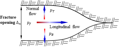
The generalized Darcy law relates the fluid flow rate and the fluid pressure in the longitudinal direction.
\begin{eqnarray*}Q_l=-k_l.\frac{\partial p}{\partial l} \end{eqnarray*}
Where,
\( k_l=\frac {\Delta^3_n}{12\mu_f} \) is the hydraulic conductivity of the discontinuity plane;
\( \mu_f \) is the fluid dynamic viscosity
On the other hand, the infiltration of the fracturing fluid into the surrounding medium can also modeled using the generalized Darcy's law as,
\begin{eqnarray*}\left.\begin{matrix} Q_T= k_T \Delta p = k_T.(p_f-p_T) \\ Q_B=k_B \Delta p=k_B(p_f-p_B) \end{matrix}\right\} \end{eqnarray*}
Where,
\( Q_T \) is the top surface fracture fluid flow;
\( Q_B \) is the bottom surface fluid flow;
\( k_T \) is the normal top surface conductivity coefficient (known as leak-off coefficient);
\( k_T \) is the normal bottom surface conductivity coefficient (known as leak-off coefficient).
1.Davila, C.G. , and Camanho, P.P. Cohesive elements for shells, NASA Langley Research Center, Virginia, USA, 2007.
2.Lewis, R. W. , & Schrefler, B. A. (1998). The finite element method in the static and dynamic deformation and consolidation of porous media (Vol. 2). John Wiley & Sons.
3.Mejia S. E.C. , Paullo. M. L. F. and Roehl, D. Continuation methods for the simulation of rock fracture with cohesive elements, ISRM congress 2015 proceedings - Int'l Symposium on Rock Mechanics, ISBN 978-1-926872-25-4.
4.Potts, D. M. and Zdravkovic, L. Finite elements analysis in geotechnical engineering and Theory, 1999. 68-70. Thomas Telford.
5.Turon, A., Costa, J., Camanho, P.P. and Davila, C.G. Simulation of delamination in composites under high-cycle fatigue, Composites Part A: applied Science and manufacturing, 2007; 22; 2270 - 2282.
6.Zielonka, M. G., Searles, K., Ning, J., Buechler, 2014. Development and validation of fully “coupled hydraulic fracturing simulation capabilities, ExxonMobil Upstream Research Company.
A reference manual documenting the set of state variables and material properties expected by the plugin, along with all of its supported configuration and result options can be found here.
 1.8.15