 |
GeMA
The GeMA main application
|
|
GeMA
The GeMA main application
|
Cell objects are a Lua wrapper over a GeMA cell (or element), providing a rich set of methods for querying and updating cell nodes and porperty bindings, among others. Cell objects can be obtained in the orchestration from a mesh object by calling the mesh:cell() method.
Example:
Most used:
Index:
cell:adjacentCell()cell:geometry()cell:numNodes()cell:numGhostNodes()cell:totalNumNodes()cell:nodeIndex()cell:nodes()cell:nodeMatrix()cell:faceNodeMatrix()cell:edgeNodeMatrix()cell:deformedNodeMatrix()cell:deformedFaceNodeMatrix()cell:deformedEdgeNodeMatrix()cell:setNodes()cell:addGhostNode()cell:removeGhostNode()cell:length()cell:area()cell:volume()cell:characteristicLength()cell:characteristicDimension()cell:centroidCartesian()cell:isValid()cell:propertyIndex()cell:setProperties()element:shape()element:linearShape()element:naturalCenter()| cell:id() | |
|---|---|
| Description: | Returns the cell id. |
| Parameters: | None. |
| Returns: | Returns the cell id number (an index between 1 and the number of mesh cells). |
Example:
| cell:mesh() | |
|---|---|
| Description: | Returns the cell mesh. |
| Parameters: | None. |
| Returns: | Returns the associated mesh object. |
Example:
| cell:type() | |
|---|---|
| Description: | Returns the cell type. |
| Parameters: | None. |
| Returns: | Returns a string with the cell type ("quad4", "tri3", ...). See the Element types page for a list of available cell types. |
Example:
| cell:active() | |
|---|---|
| Description: | Checks if the cell is active or not. Inactive cells do not take part in analysis processes. |
| Parameters: | None. |
| Returns: | Returns true if the cell is active, false if not. |
Example:
| cell:setActive(active) | |
|---|---|
| Description: | Marks the cell as active or not. |
| Parameters: | active - A boolean with the new cell state. |
| Returns: | Nothing. |
Example:
| cell:adjacentCell(sideIndex) | |
|---|---|
| Description: | Given a cell side index (edge index for surface elements or face index for solid elements, undefined for line elements), returns the adjacent cell by that side or nil if that side is at the mesh border. Also returns the index of the neighbor side in the adjacent cell. IMPORTANT: This function should only be called if mesh:hasCapability("topology") returns true. |
| Parameters: | sideIndex - The index of the side whose adjacent neighbor will be queried. It should be an edge local index (a value between 1 and geometry:numEdges()) for surface elements and a face local index (a value between 1 and geometry:numFaces()) for solid elements. See the Element types page for the edge and face organization for each cell type. |
| Returns: | Returns the adjacent cell object or nil if there is none (border side). If there is an adjacent side, also returns the index of the neighbor side at the adjacent cell. |
Example:
| cell:geometry() | |
|---|---|
| Description: | Returns a cell geometry object that can be used to query several cell geometric properties, like the number of the cell edges and faces, the number of nodes per edge / face, etc. |
| Parameters: | None. |
| Returns: | Returns a cell geometry object. |
Example:
| cell:numNodes() | |
|---|---|
| Description: | Returns the number of geometry nodes in the cell. |
| Parameters: | None. |
| Returns: | Returns the number of nodes in this cell. |
Example:
| cell:numGhostNodes() | |
|---|---|
| Description: | Returns the number of ghost nodes in the cell. |
| Parameters: | None. |
| Returns: | Returns the number of ghost nodes in this cell. |
Example:Returns a cell geometry object
| cell:totalNumNodes() | |
|---|---|
| Description: | Returns the total number of nodes in the cell (geometry + ghost). |
| Parameters: | None. |
| Returns: | Returns the total number of nodes (gemotry + ghost) in this cell. |
Example:
| cell:nodeIndex(localIndex) | |
|---|---|
| Description: | Returns the global mesh node index of the given local cell node index. |
| Parameters: | localIndex - The local node index number. Local indices are numbered from 1 to cell:numNodes() for common cell nodes, i.e., for those nodes that take part in the cell geometry definition. Ghost nodes, on the other hand are numbered from cell:numNodes()+1 to cell:totalNumNodes(). For the set of 'geometry' nodes, their precise local order in the cell depends on the cell type. For the set of 'ghost' nodes, their order follows the order in which ghost nodes where added to the cell. |
| Returns: | Returns the global mesh node index number of the given local index. It is a number from 1 to mesh:numNodes() if localIndex is a 'geometry' index and a value from 1 to mesh:numGhostNodes() WITH the highest bit set if localIndex is a 'ghost' index. |
Example:
| cell:nodes(ghost) | |
|---|---|
| Description: | Returns a table filled with the set of cell global node indices. It is equivalent to calling cell:nodeIndex(i), with i varying from 1 to n, where n is either the result of cell:numNodes() if ghost was set to false or the result of cell:totalNumNodes() if ghost was set to true, and collecting the results on a table. |
| Parameters: | ghost - Optional parameter defining if ghost nodes should be added to the returned table or not. If not given, ghost nodes will not be added to the table. |
| Returns: | Returns the table filled with the set of cell global node indices. Ghost nodes in the table, if any, will have its highest bit set (see the description for the cell:nodeIndex() function). |
Example:
| cell:nodeMatrix(coordAccessor, transposed, mode) | |||
|---|---|---|---|
| Description: | Returns a matrix object filled with the cell's node coordinates. By default, node coordinates are given in the matrix rows but the matrix can also be created with coordinates in columns if transposed is set tor true. The optional mode parameter controls which cell nodes will appear in the matrix. | ||
| Parameters: | coordAccessor | An accessor for the mesh node coordinates (see mesh:nodeCoordAccessor()). | |
| transposed | An optional boolean defining if the result matrix should be transposed or not. Default = false. | ||
| mode | An optional mode parameter defining which nodes should be included in the result. Accepted values are (the image on the side shows a quad8 element with four additional ghost nodes in green): - "nodes" Fill matrix with cell geometry nodes only (nodes 1 to 8 on the image); - "vertices" Fill matrix matrix with geometry linear corner nodes only (nodes 1 to 4 on the image); - "ghost" Fill matrix with ghost nodes only (nodes 9 to 12 on the image); - "all" Fill matrix with all cell nodes (nodes 1 to 12 on the image); Default = "nodes". | 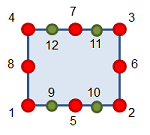
| |
| Returns: | Returns a 'n x d' node coordinate matrix object (n = number of nodes in the cell, d is the coordinate dimension) where line 'i' holds the coordinates of node 'i'. If transposed == true, the returned matrix is a 'd x n' matrix and now column 'i' holds the coordinates of node 'i'. | E.g.: tri3, n=3, d=2: \(\begin{pmatrix} x_1 & y_1 \\ x_2 & y_2 \\ x_3 & y_3 \end{pmatrix}\) | |
Example:
| cell:faceNodeMatrix(coordAccessor, faceIndex, transposed, mode) | ||
|---|---|---|
| Description: | Similar to cell:nodeMatrix(), returns a matrix object filled with the node coordinates fot the cell's given face, organized according to the equivalent face element node ordering, as returned by geometry:faceElement(). By default, node coordinates are given in the matrix rows but the matrix can also be created with coordinates in columns if transposed is set tor true. The optional mode parameter controls which cell nodes will appear in the matrix. | |
| Parameters: | coordAccessor | An accessor for the mesh node coordinates (see mesh:nodeCoordAccessor()). |
| faceIndex | The face number (between 1 and geometry:numFaces()). See the Element types page for the face organization for each cell type. | |
| transposed | An optional boolean defining if the result matrix should be transposed or not. Default = false. | |
| mode | An optional mode parameter defining which nodes should be included in the result. Accepted values are: - "nodes" Fill matrix with cell geometry nodes only; - "vertices" Fill matrix matrix with geometry linear corner nodes only; Default = "nodes". | |
| Returns: | Returns a 'n x d' node coordinate matrix object (n = number of nodes in the cell, d is the coordinate dimension) where line 'i' holds the coordinates of node 'i'. If transposed == true, the returned matrix is a 'd x n' matrix and now column 'i' holds the coordinates of node 'i'. Important: This function returns an error if called for a face where the corresponding call to geometry:faceElement(faceIndex) (or to geometry:faceLinearElement(faceIndex) if mode is "vertices") returns nil (which includes surface elements). | |
Example:
| cell:edgeNodeMatrix(coordAccessor, edgeIndex, transposed, mode) | ||
|---|---|---|
| Description: | Similar to cell:nodeMatrix(), returns a matrix object filled with the node coordinates fot the cell's given edge, organized according to the equivalent edge element node ordering, as returned by geometry:edgeElement(). By default, node coordinates are given in the matrix rows but the matrix can also be created with coordinates in columns if transposed is set tor true. The optional mode parameter controls which cell nodes will appear in the matrix. | |
| Parameters: | coordAccessor | An accessor for the mesh node coordinates (see mesh:nodeCoordAccessor()). |
| edgeIndex | The edge number (between 1 and geometry:numEdges()). See the Element types page for the face organization for each cell type. | |
| transposed | An optional boolean defining if the result matrix should be transposed or not. Default = false. | |
| mode | An optional mode parameter defining which nodes should be included in the result. Accepted values are: - "nodes" Fill matrix with cell geometry nodes only; - "vertices" Fill matrix matrix with geometry linear corner nodes only; Default = "nodes". | |
| Returns: | Returns a 'n x d' node coordinate matrix object (n = number of nodes in the cell, d is the coordinate dimension) where line 'i' holds the coordinates of node 'i'. If transposed == true, the returned matrix is a 'd x n' matrix and now column 'i' holds the coordinates of node 'i'. Important: This function returns an error if called for an edge where the corresponding call to geometry:edgeElement(edgeIndex) (or to geometry:edgeLinearElement(edgeIndex) if mode is "vertices") returns nil (which includes bar elements). | |
Example:
| cell:deformedNodeMatrix(coordAccessor, uAccessor, transposed, mode) | |||
|---|---|---|---|
| Description: | Similar to cell:nodeMatrix(), returns a matrix object filled with the cell's node coordinates with added deformation as given by uAccessor. By default, the deformed node coordinates are given in the matrix rows but the matrix can also be created with coordinates in columns if transposed is set tor true. The optional mode parameter controls which cell nodes will appear in the matrix. | ||
| Parameters: | coordAccessor | An accessor for the mesh node coordinates (see mesh:nodeCoordAccessor()). | |
| uAccessor | An accessor for the node attribute or state variable storing the deformation values that will be added to the node coordinates. | ||
| transposed | An optional boolean defining if the result matrix should be transposed or not. Default = false. | ||
| mode | An optional mode parameter defining which nodes should be included in the result. Accepted values are (the image on the side shows a quad8 element with four additional ghost nodes in green): - "nodes" Fill matrix with cell geometry nodes only (nodes 1 to 8 on the image); - "vertices" Fill matrix matrix with geometry linear corner nodes only (nodes 1 to 4 on the image); Default = "nodes". |
| |
| Returns: | Returns a 'n x d' node coordinate matrix object (n = number of nodes in the cell, d is the coordinate dimension) where line 'i' holds the deformed coordinates of node 'i'. Also returns a vector of size 'n*d' filled with the deformation values obtained from uAccessor. This vector is organized per node. If transposed == true, the returned matrix is a 'd x n' matrix and now column 'i' holds the coordinates of node 'i'. | E.g.: tri3, n=3, d=2: \(\begin{pmatrix} x_1 & y_1 \\ x_2 & y_2 \\ x_3 & y_3 \end{pmatrix}\), \(\begin{pmatrix} u_{x1} & u_{y1} & u_{x2} & u_{y2} & u_{x3} & u_{y3} \end{pmatrix}\) | |
Example:
| cell:deformedFaceNodeMatrix(coordAccessor, uAccessor, faceIndex, transposed, mode) | ||
|---|---|---|
| Description: | Similar to cell:deformedNodeMatrix(), returns a matrix object filled with the node coordinates for the cell's given face, organized according to the equivalent face element node ordering, as returned by geometry:faceElement(), with added deformation as given by uAccessor. By default, the deformed node coordinates are given in the matrix rows but the matrix can also be created with coordinates in columns if transposed is set tor true. The optional mode parameter controls which cell nodes will appear in the matrix. | |
| Parameters: | coordAccessor | An accessor for the mesh node coordinates (see mesh:nodeCoordAccessor()). |
| uAccessor | An accessor for the node attribute or state variable storing the deformation values that will be added to the node coordinates. | |
| faceIndex | The face number (between 1 and geometry:numFaces()). See the Element types page for the face organization for each cell type. | |
| transposed | An optional boolean defining if the result matrix should be transposed or not. Default = false. | |
| mode | An optional mode parameter defining which nodes should be included in the result. Accepted values are: - "nodes" Fill matrix with cell geometry nodes only; - "vertices" Fill matrix matrix with geometry linear corner nodes only; Default = "nodes". | |
| Returns: | Returns a 'n x d' node coordinate matrix object (n = number of nodes in the cell, d is the coordinate dimension) where line 'i' holds the deformed coordinates of node 'i'. Also returns a vector of size 'n*d' filled with the deformation values obtained from uAccessor. This vector is organized per node. If transposed == true, the returned matrix is a 'd x n' matrix and now column 'i' holds the coordinates of node 'i'. Important: This function returns an error if called for a face where the corresponding call to geometry:faceElement(faceIndex) (or to geometry:faceLinearElement(faceIndex) if mode is "vertices") returns nil (which includes surface elements). | |
Example:
| cell:deformedEdgeNodeMatrix(coordAccessor, uAccessor, edgeIndex, transposed, mode) | ||
|---|---|---|
| Description: | Similar to cell:deformedNodeMatrix(), returns a matrix object filled with the node coordinates for the cell's given edge, organized according to the equivalent edge element node ordering, as returned by geometry:edgeElement(), with added deformation as given by uAccessor. By default, the deformed node coordinates are given in the matrix rows but the matrix can also be created with coordinates in columns if transposed is set tor true. The optional mode parameter controls which cell nodes will appear in the matrix. | |
| Parameters: | coordAccessor | An accessor for the mesh node coordinates (see mesh:nodeCoordAccessor()). |
| uAccessor | An accessor for the node attribute or state variable storing the deformation values that will be added to the node coordinates. | |
| edgeIndex | The edge number (between 1 and geometry:numEdges()). See the Element types page for the face organization for each cell type. | |
| transposed | An optional boolean defining if the result matrix should be transposed or not. Default = false. | |
| mode | An optional mode parameter defining which nodes should be included in the result. Accepted values are: - "nodes" Fill matrix with cell geometry nodes only; - "vertices" Fill matrix matrix with geometry linear corner nodes only; Default = "nodes". | |
| Returns: | Returns a 'n x d' node coordinate matrix object (n = number of nodes in the cell, d is the coordinate dimension) where line 'i' holds the deformed coordinates of node 'i'. Also returns a vector of size 'n*d' filled with the deformation values obtained from uAccessor. This vector is organized per node. If transposed == true, the returned matrix is a 'd x n' matrix and now column 'i' holds the coordinates of node 'i'. Important: This function returns an error if called for an edge where the corresponding call to geometry:edgeElement(edgeIndex) (or to geometry:edgeLinearElement(edgeIndex) if mode is "vertices") returns nil (which includes bar elements). | |
Example:
| cell:setNodes(nodeTable) | |
|---|---|
| Description: | Updates the cell node list. Usually called after inserting new cells on the mesh. |
| Parameters: | nodeTable - A table storing a list with the new set of cell nodes. Nodes should be organized according to the element type node organization schema. Its size should be equal to cell:numNodes() (i.e the node table should include geometry nodes only). To add ghost nodes to the cell, refer to cell:addGhostNode(). |
| Returns: | Nothing |
Example:
| cell:addGhostNode(globalIndex) | |
|---|---|
| Description: | Adds a new ghost node to the cell, returning its local index (its index inside the cell's node list). |
| Parameters: | globalIndex - A global node mesh index (either with or without the highest bit set) defining the existing mesh ghost node that will be added to the cell. |
| Returns: | The node's local index inside the cell. |
Example:
| cell:removeGhostNode(localIndex) | |
|---|---|
| Description: | Removes a ghost node from the cell. Keep in mind that this operation does not removes the ghost node from the mesh, only from the cell definition. |
| Parameters: | localIndex - The ghost node local cell index. |
| Returns: | Nothing. |
Example:
| cell:length(coordAccessor, edgeIndex, mode) cell:length(X, edgeIndex, mode) | ||
|---|---|---|
| Description: | Returns the length of a bar element with nodes defined by the given accessor or X coordinate matrix. Can also be used for calculating the length of a 2D interface element (the length is calculated at the average "plane" between the interface element edges) or the length of a 2D/3D element's edge. The length of linear elements/edges is calculated geometrically while the length of quadratic elements/edges is calculated by numeric integration using the element's default integration rule. If you already have a filled coordinate matrix, passing it to the length method is more efficient than providing the coordinate accessor, which in the end will be used to fill an internal coordinate matrix. Just make sure that your matrix was filled with the correct "nodes in columns" orientation. You can always passed the transposed matrix if needed. | |
| Parameters: | coordAccessor | An accessor for the mesh node coordinates (see mesh:nodeCoordAccessor()). |
| X | A matrix with the element's node coordinates. Should be organized as a d x n matrix where d is the coordinate dimension (as returned by geometry:numCoord()) and n is the number of nodes in the cell (as returned by geometry:numNodes()). Can be filled either manually or by a call to cell:nodeMatrix(coordAccessor, true) or to cell:deformedNodeMatrix(coordAccessor, true) to take node deformation in consideration (needed for mid plane interface element calculations). | |
| edgeIndex | Optional edge number (between 1 and geometry:numEdges()) for 2D and 3D elements. See the Element types page for the edge organization for each cell type. If you want to give a mode parameter when calculating the length of a bar (or 2D interface) element, just pass 1 as the edge number. | |
| mode | Optional flag accepting the values "linear" or "element". When set to "linear", informs the method that quadratic elements can have their length calculated as if the element was a linear one. Usefull when you know that your quadratic elements have a linear geometry. Should not be used if the coordinates where given by a matrix that takes into account deformations. When set to "element", the element's type will be respected. When set to nil (the default), the mode defined on the mesh will be used. Unless changed, it will be equal to "element". | |
| Returns: | For 1D elements or 2D interface elements, returns the cell length. For 2D and 3D elements, returns the length of the given element's edge. | |
Example:
| cell:area(coordAccessor, faceIndex, mode) cell:area(X, faceIndex, mode) | ||
|---|---|---|
| Description: | Returns the area of a surface element with nodes defined by the given accessor or X coordinate matrix. Can also be used for calculating the area of a 3D interface element (the area is calculated at the average "plane" between the interface element faces) or the area of a 3D element's face. The area of linear elements/faces is calculated geometrically while the area of quadratic elements/faces is calculated by numeric integration using the element's default integration rule. If you already have a filled coordinate matrix, passing it to the area method is more efficient than providing the coordinate accessor, which in the end will be used to fill an internal coordinate matrix. Just make sure that your matrix was filled with the correct "nodes in columns" orientation. You can always passed the transposed matrix if needed. | |
| Parameters: | coordAccessor | An accessor for the mesh node coordinates (see mesh:nodeCoordAccessor()). |
| X | A matrix with the element's node coordinates. Should be organized as a d x n matrix where d is the coordinate dimension (as returned by geometry:numCoord()) and n is the number of nodes in the cell (as returned by geometry:numNodes()). Can be filled either manually or by a call to cell:nodeMatrix(coordAccessor, true) or to cell:deformedNodeMatrix(coordAccessor, true) to take node deformation in consideration (needed for mid plane interface element calculations). | |
| faceIndex | Optional face number (between 1 and geometry:numFaces()) for 3D elements. See the Element types page for the face organization for each cell type. If you want to give a mode parameter when calculating the area of a surface (or 3D interface) element, just pass 1 as the face number. | |
| mode | Optional flag accepting the values "linear" or "element". When set to "linear", informs the method that quadratic elements can have their area calculated as if the element was a linear one. Usefull when you know that your quadratic elements have a linear geometry. Should not be used if the coordinates where given by a matrix that takes into account deformations. When set to "element", the element's type will be respected. When set to nil (the default), the mode defined on the mesh will be used. Unless changed, it will be equal to "element". | |
| Returns: | For (non interface) 2D elements or 3D interface elements, returns the cell area. For 3D elements, returns the area of the given element's face. For 1D elements or 2D interface elements, retuns 0.0. | |
Example:
| cell:volume(coordAccessor, mode) cell:volume(X, mode) | ||
|---|---|---|
| Description: | Returns the volume of a solid element with nodes defined by the given accessor or X coordinate matrix. The area of linear elements is calculated geometrically while the area of quadratic elements is calculated by numeric integration using the element's default integration rule. If you already have a filled coordinate matrix, passing it to the volume method is more efficient than providing the coordinate accessor, which in the end will be used to fill an internal coordinate matrix. Just make sure that your matrix was filled with the correct "nodes in columns" orientation. You can always passed the transposed matrix if needed. | |
| Parameters: | coordAccessor | An accessor for the mesh node coordinates (see mesh:nodeCoordAccessor()). |
| X | A matrix with the element's node coordinates. Should be organized as a d x n matrix where d is the coordinate dimension (as returned by geometry:numCoord()) and n is the number of nodes in the cell (as returned by geometry:numNodes()). Can be filled either manually or by a call to cell:nodeMatrix(coordAccessor, true) or to cell:deformedNodeMatrix(coordAccessor, true) to take node deformation in consideration. | |
| mode | Optional flag accepting the values "linear" or "element". When set to "linear", informs the method that quadratic elements can have their volume calculated as if the element was a linear one. Usefull when you know that your quadratic elements have a linear geometry. Should not be used if the coordinates where given by a matrix that takes into account deformations. When set to "element", the element's type will be respected. When set to nil (the default), the mode defined on the mesh will be used. Unless changed, it will be equal to "element". | |
| Returns: | For (non interface) 3D elements, returns the cell volume. For 1D, 2D or 3D interface elements, retuns 0.0. | |
Example:
| cell:characteristicLength(coordAccessor, mode) cell:characteristicLength(X, mode) | ||
|---|---|---|
| Description: | Returns the characteristic length of the element with nodes defined by the given accessor or X coordinate matrix. It is defined as the length for bar and surface interface elements, the square root of the area for (non iterface) surface and solid interface elements and the cubic root of the volume for (non interface) solid elements. If you already have a filled coordinate matrix, passing it to the characteristic length method is more efficient than providing the coordinate accessor, which in the end will be used to fill an internal coordinate matrix. Just make sure that your matrix was filled with the correct "nodes in columns" orientation. You can always passed the transposed matrix if needed. | |
| Parameters: | coordAccessor | An accessor for the mesh node coordinates (see mesh:nodeCoordAccessor()). |
| X | A matrix with the element's node coordinates. Should be organized as a d x n matrix where d is the coordinate dimension (as returned by geometry:numCoord()) and n is the number of nodes in the cell (as returned by geometry:numNodes()). Can be filled either manually or by a call to cell:nodeMatrix(coordAccessor, true) or to cell:deformedNodeMatrix(coordAccessor, true) to take node deformation in consideration. | |
| mode | Optional flag accepting the values "linear" or "element". When set to "linear", informs the method that quadratic elements can have their characteristic length calculated as if the element was a linear one. Usefull when you know that your quadratic elements have a linear geometry. Should not be used if the coordinates where given by a matrix that takes into account deformations. When set to "element", the element's type will be respected. When set to nil (the default), the mode defined on the mesh will be used. Unless changed, it will be equal to "element". | |
| Returns: | Returns the calculated characteristic length. | |
Example:
| cell:characteristicDimension(coordAccessor, mode) cell:characteristicDimension(X, mode) | ||
|---|---|---|
| Description: | Returns the characteristic dimension of the element with nodes defined by the given accessor or X coordinate matrix. It is defined as the length for bar and surface interface elements, the area for (non iterface) surface and solid interface elements and the volume for (non interface) solid elements. If you already have a filled coordinate matrix, passing it to the characteristic dimension method is more efficient than providing the coordinate accessor, which in the end will be used to fill an internal coordinate matrix. Just make sure that your matrix was filled with the correct "nodes in columns" orientation. You can always passed the transposed matrix if needed. | |
| Parameters: | coordAccessor | An accessor for the mesh node coordinates (see mesh:nodeCoordAccessor()). |
| X | A matrix with the element's node coordinates. Should be organized as a d x n matrix where d is the coordinate dimension (as returned by geometry:numCoord()) and n is the number of nodes in the cell (as returned by geometry:numNodes()). Can be filled either manually or by a call to cell:nodeMatrix(coordAccessor, true) or to cell:deformedNodeMatrix(coordAccessor, true) to take node deformation in consideration. | |
| mode | Optional flag accepting the values "linear" or "element". When set to "linear", informs the method that quadratic elements can have their characteristic dimension calculated as if the element was a linear one. Usefull when you know that your quadratic elements have a linear geometry. Should not be used if the coordinates where given by a matrix that takes into account deformations. When set to "element", the element's type will be respected. When set to nil (the default), the mode defined on the mesh will be used. Unless changed, it will be equal to "element". | |
| Returns: | Returns the calculated characteristic dimension. | |
Example:
| cell:centroidCartesian(coordAccessor, mode) cell:centroidCartesian(X, mode) | ||
|---|---|---|
| Description: | Returns a vector with the cartesian coordinates for the centroid of the element with nodes defined by the given accessor or X coordinate matrix. Whenever possible, the calculations are done geometrically. For quadratic elements, it is done by numerical integration. For interface elements it is done at the element's "middle plane". If you already have a filled coordinate matrix, passing it to the centroid method is more efficient than providing the coordinate accessor, which in the end will be used to fill an internal coordinate matrix. Just make sure that your matrix was filled with the correct "nodes in columns" orientation. You can always passed the transposed matrix if needed. | |
| Parameters: | coordAccessor | An accessor for the mesh node coordinates (see mesh:nodeCoordAccessor()). |
| X | A matrix with the element's node coordinates. Should be organized as a d x n matrix where d is the coordinate dimension (as returned by geometry:numCoord()) and n is the number of nodes in the cell (as returned by geometry:numNodes()). Can be filled either manually or by a call to cell:nodeMatrix(coordAccessor, true) or to cell:deformedNodeMatrix(coordAccessor, true) to take node deformation in consideration. | |
| mode | Optional flag accepting the values "linear" or "element". When set to "linear", informs the method that quadratic elements can have their centroid calculated as if the element was a linear one. Usefull when you know that your quadratic elements have a linear geometry. Should not be used if the coordinates where given by a matrix that takes into account deformations. When set to "element", the element's type will be respected. When set to nil (the default), the mode defined on the mesh will be used. Unless changed, it will be equal to "element". | |
| Returns: | Returns a vector object with the cell centroid in cartesian coordinates. | |
Example:
| cell:isValid(coordAccessor) | |
|---|---|
| Description: | Checks the cell geometry to verify if it is a valid cell (consistent, not self intersecting and convex). |
| Parameters: | coordAccessor - An accessor for the mesh node coordinates (see mesh:nodeCoordAccessor()). |
| Returns: | Returns true if the cell is valid, false otherwise. |
Example:
| cell:propertyIndex(psetIndex) | |
|---|---|
| Description: | Given a property set number, returns the line of the property set that contains property values for this cell. |
| Parameters: | psetIndex - The property set index inside the mesh. A number between 1 and mesh:numPropertySets(). |
| Returns: | Returns the property set line associated to this cell. |
Example:
| cell:setProperties(propTable) | |
|---|---|
| Description: | Updates the cell list defining which property set rows are associated with this cell, for every property set. Usually called after inserting new cells on the mesh. |
| Parameters: | propTable - A table storing a list with the new set of cell property rows. The list should have size equal to mesh:numPropertySets() and each index should be inside the range of rows for the respective property set. Property set order is the same as the order in which property sets where added to the mesh and can be queried by mesh:propertySets(). |
| Returns: | Nothing. |
Example:
| element:shape() | |
|---|---|
| Description: | Returns the element shape function object. Keep in mind that this method is not available if the cell belongs to a "cell mesh" and not to an "element mesh". |
| Parameters: | None. |
| Returns: | Returns the shape function object associated with this element type. |
Example:
| element:linearShape() | |
|---|---|
| Description: | For quadratic elements, returns the element equivalent linear shape function object (for a quad9 element, for example, returns a quad4 shape function). Otherwise, returns the same shape function as the element:shape() method. Keep in mind that this method is not available if the cell belongs to a "cell mesh" and not to an "element mesh". |
| Parameters: | None. |
| Returns: | Returns the linear shape function object associated with this element type. |
Example:
| element:naturalCenter() | ||
|---|---|---|
| Description: | Returns a vector with the natural coordinates for the reference element's center. Keep in mind that converting the returned natural coordinate to a cartesian coordinate (by calling shape:cartesianToNatural()), in general, is not equal to the element's centroid, as returned by cell:centroidCartesian(). | |
| Parameters: | None. | |
| Returns: | Returns a vector object with the element center in natural coordinates. | |
Example:
| element:hPOrder() | |
|---|---|
| Description: | Returns the element's polynomial interpolation order for scalar fields. This is the same value as returned by the element's mesh homonymous method: mesh:hPOrder(). Keep in mind that this method is only available for hierarchical elements. |
| Parameters: | None. |
| Returns: | Returns the element's polynomial interpolation order for scalar fields. |
Example:
| element:hQOrder() | |
|---|---|
| Description: | Returns the element's polynomial interpolation order for vector fields. This is the same value as returned by the element's mesh homonymous method: mesh:hQOrder(). Keep in mind that this method is only available for hierarchical elements. |
| Parameters: | None. |
| Returns: | Returns the element's polynomial interpolation order for vector fields. |
Example:
 1.8.15