 |
GeMA
The GeMA main application
|
|
GeMA
The GeMA main application
|
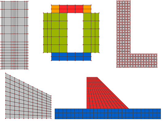
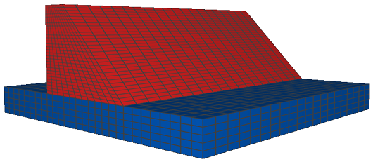
MeshLib is a set of utilitary functions for creating 2D and 3D, "grid like", meshes. By partitioning the regular 2D grid into smaller blocks that can be included, or not, in the final mesh, and also by allowing the user to vary grid column and line positions on both horizontal and vertical grid borders, meshes such as the examples below can be easily created. 3D meshes are extruded versions of 2D grids. It supports both quadrilateral and triangular 2D meshes with linear or quadratic elements, material associations and attribute initialization. For 3D meshes, it supports linear and quadratinc hexahedrons.
It also features functions to add interface elements to 2D meshes and to save meshes to model files. Those functions work with meshes created by MeshLib and also with meshes created manually or with the help of a pre-processor. See the MeshLib example, on the examples page for a comprehensive usage tutorial that reviews most of the options presented by MeshLib.
Important: Please rememeber that the library must be loaded, before the first call to one of its exported methods, by a call to dofile("$SCRIPTS/meshLib.lua").
Index:
meshLib.build2DGrid()meshLib.regularSpacing()meshLib.expSpacing()meshLib.densitySpacing()meshLib.merge()meshLib.build3DGrid()meshLib.addInterfaceElementsTo2DMesh()meshLib.add2DMeshEdgesToPathList()meshLib.saveMeshToModelFile()| meshLib.build2DGrid(elemType, xPoints, yPoints, blockList, matList, options) | ||
|---|---|---|
| Description: | Given an element type and lists with x and y coordinates for the 2D grid's columns and lines, returns tables with grid nodes, cells and borders. An optional block list enables the definition of grids composed by several rectangular blocks, allowing for the creation of meshes with multiple geometries, including holes, and also for easily specifying zones with different materials. Also, optional node and cell functions allows for the user to initialize node and cell attributes and state variable values. An optional material list allows for specifying materials for cell groups. By default, borders named gridLeft, gridRight, gridTop and gridBottom are returned in the border table. That behaviour can be changed by providing a user table specifying the desired borders. Interface elements can be added to the mesh by giving a set of edge paths where the elements should be inserted. They can also be added by block with the interface key. See below. | |
| Parameters: | elemType | The grid element type. Accepted values are "quad4", "quad8", "quad9", "tri3" and "tri6". |
| xPoints | A table with grid column coordinates. | |
| yPoints | A table with grid line coordinates. | |
| blockList | An optional table with block definitions. Contains one entry for each vertical section of the grid, storing the section Y limits followed by n > 1 X sections. Each X section is a table with the X limits of that section. If not given, a single block spaning the whole grid will be used. The example below better illustrates the format. Y intervals in the blockList rows must span the whole grid, without gaps or overlaps. They should also be given in increasing Y order. X limits should also be given in increasing X order. X sections from the same Y section must not overlap. All X and Y coordinates given in the block list must be present in xPoints / yPoints. X section definitions can also include a cellGroup tag identifying the group name for this cell block in the mesh. It can also contain tags with propertySet names storing the material row for the cell block (for this option to work, the matList parameter must be provided). An interface tag allows the user to specify that edges inside this block should be replaced by interface elements. This tag value should be a string composed by the desired combination of letters "h", "v" and "d" controling the edge directions that will receive interface elements. A value equal to "hd", for example, means that horizontal and diagonal edges will be replaced, while a value of "hvd" means that all edges, horizontal, vertical and diagonal, will be replaced ("d" flag is ignored for quad meshes). If interface is given, an aditional tag interfaceMatList can be used to provide the material binding for this block interface elements. If given, it should be a table with property set / value pairs. If not given, the blockList material definition will be used, reverting to defaults if those are also absent. | |
| matList | An optional table with a map keyed by the property sets associated with the mesh, storing their default value. Those map keys will be used to retrieve materials from the blockList, using the default if not specified in the block. This table will be ignored if a block function is provided in the options table. | |
| options | An optional table joining several control options for the function behaviour. Only options different from the default need to be filled. They are: - borders Optional table describing the desired border definitions. If absent, borders for the left, right, top and bottom of the grid will be returned, named gridLeft, gridRight, gridTop and gridBottom. When given, each table row specifies a border, consisting of a border name followed by a sequence of sub-tables defining block borders belonging to this definition. Each sub-table consists of a block number followed by a side name and optionally followed by an interval. The block number is defined by its order inside the blocks defined in blockList (first block corresponds to the first X interval of the first Y interval, second block to the second X interval of the first Y interval and so on). The side name is one of "left", "right", "top" or "bottom". The interval gives the coordinates of the beginning of the first edge and ending of the last block edge to be included in the border. If absent, the whole block side will be included. Remember that the given coordinates must belong to the block. - interfaceList Optional table with the definition of edges in the mesh where interface elements should be inserted. Contains a list of paths, each composed by a set of node coordinates. Coordinates must be compatible with mesh nodes and each consecutive pair of nodes in a path must correspond to a mesh edge (duplicate and border edges will be ignored). Each path can also contain tags with propertySet names storing the material row for the interface cells in that path (depends on a matList being given). An optional tag pathIndex can contain a value that will be passed for cellf when an interface element is created. If absent, that value will be the path index in interfaceList. - interfaceOptions Optional table with additional options used when adding interface elements. Available fields are: hasMidNode, useQuad4, offset, matList and cellf (details on the documentation for meshLib.addInterfaceElementsTo2DMesh()). The last two (matList and cellf), if nil will be automatically filled with matList and options.cellf, respectivelly. - useGridCoords If set to true, cartesian coordinates given in blockList, borders, interfaceList, midxLine and midyColumn are replaced by lines and columns. This is interesting when using functions to create the set of grid coordinates and the only practical way to give an interfaceList for trapezoid like grids (when using topxPoints and / or rightyPoints). For blockList and borders, the structure remains the same, changing X coordinates by column indices and Y coordinates by line indices. For the interfaceList, coordinate order is reversed so (X, Y) pairs are replaced by the more traditional (line, column) coordinates. | |
- topxPoints An optional table containing a second set of column coordinates. When given, the first set in xPoints will be used for the first line (bottom) and this one for the last line (top). Intermediate coordinates will be linear interpolated. - midxPoints An optional table containing a third set of column coordinates. When given, the first set in xPoints will be used for the first line (bottom), this one for an intermediate line, given by options.midxLine, and topxPoints for the last line (top). Intermediate coordinates will be linear interpolated, either between xPoints and midxPoints or between midxPoints and topxPoints. - midxLine The reference line for midxPoints. Must be given if midxPoints was given. Should be given as an Y coordinate or a line index if useGridCoords = true. - rightyPoints An optional table containing a second set of line coordinates. When given, the first set in yPoints will be used for the first column (left) and this one for the last column (right). Intermediate coordinates will be linear interpolated. - midyPoints An optional table containing a third set of column coordinates. When given, the first set in yPoints will be used for the first column (left), this one for an intermediate column, given by options.midyColumn, and rightyPoints for the last column (right). Intermediate coordinates will be linear interpolated, either between yPoints and midyPoints or between midyPoints and rightyPoints. - midyColumn The reference column for midyPoints. Must be given if midyPoints was given. Should be given as an X coordinate or a column index if useGridCoords = true. | ||
| - nodef Optional function called whenever a new node is added to the mesh. Receives as parameter the table with node coordinates. The function can add state variable and attribute values to the given table, as if in a standard node cell definition. It can also be used to update the given node coordinates. This can be used to create parametric surfaces. - cellf Optional function called whenever a new cell is added to the mesh. Receives as parameters the cell definition table, filled with cell nodes only, and a reference to the node list, allowing the user to recover cell node coordinates if needed. The function should add cell attribute and property values to the given cell table, as if in a standard element nodes definition. Also called when adding interface elements to the mesh. On that case, an aditional third parameter is given with the corresponding path index for elements given by interfaceList entries or the block index for interface elements created by an interface tag in the blockList. - blockf Optional function called whenever a new cell group is added to the mesh. Receives as parameters the cell group table definition, the corresponding block number and a reference for the X section that originated this cell group. The function should add default property definitions for the group to the given table. | ||
| Returns: | Returns the node list, cell groups list and boundaries list, all in the format expected by the standard GemaMesh plugin. | |
Example:
| meshLib.regularSpacing(first, last, n) | ||
|---|---|---|
| Description: | Given the coordinates of the first and last points, first < last, and the number of desired intervals n, returns a table with n + 1 points splitting the space between first and last into n intervals of equal size. This function is meant to be used for helping to create the point lists passed as parameter to meshLib.build2DGrid(). | |
| Parameters: | first | The first coordinate in the returned table. |
| last | The last coordinate in the returned table (must be greater than first). | |
| n | The desired number of intervals. | |
| Returns: | Returns a table filled with n+1 point coordinates, starting at first and ending with last. | |
Example:
| meshLib.expSpacing(first, last, n, bias, reverse) | ||
|---|---|---|
| Description: | Given the coordinates of the first and last points, first < last, and the number of desired intervals n, returns a table with n + 1 points splitting the space between first and last into n intervals whose distance between them increases (or decreases if reverse is true) in an exponential way controled by the bias factor. A factor of 10 means that the last segment length will be 10 times the length of the first segment. This function is meant to be used for helping to create the point lists passed as parameter to meshLib.build2DGrid(). | |
| Parameters: | first | The first coordinate in the returned table. |
| last | The last coordinate in the returned table (must be greater than first). | |
| n | The desired number of intervals. | |
| bias | The bias factor controling the exponential grow. A factor of 10 means that the last segment length will be 10 times the length of the first segment. | |
| reverse | An optional boolean value that when set to true reverses the segments order, so that the first segment will be the biggest one and the last the smaller. | |
| Returns: | Returns a table filled with n+1 point coordinates, starting at first and ending with last. | |
Example:
| meshLib.densitySpacing(first, last, n, densityf) | ||
|---|---|---|
| Description: | Given the coordinates of the first and last points, first < last, and the number of desired intervals n, returns a table with n + 1 points splitting the space between first and last into n intervals whose distance between them is given by the density function densityf. This function is meant to be used for helping to create the point lists passed as parameter to meshLib.build2DGrid(). | |
| Parameters: | first | The first coordinate in the returned table. |
| last | The last coordinate in the returned table (must be greater than first). | |
| n | The desired number of intervals. | |
| densityf | A Lua function that will be evaluated between 0 and 1 (0 = first, last = 1). Its relative value determines the grid density on the region. It must be a positive function, with higher values meaning denser spacing. The used algorithm calculates the area beneath the curve and spreads points in a way that the area between each point is equal. | |
| Returns: | Returns a table filled with n+1 point coordinates, starting at first and ending with last. | |
Example:
| meshLib.merge(...) | ||
|---|---|---|
| Description: | Given a set of two or more tables with increasing coordinates, and each table starting at a coordinate greater than or equal to the last coordinate of the previous one, joins the coordinates into a single ordered table. This function is meant to be used for helping to create the point lists passed as parameter to meshLib.build2DGrid(). | |
| Parameters: | ... - A set of two or more tables. | |
| Returns: | Returns a table with the merged contents of its input tables. | |
Example:
| meshLib.build3DGrid(elemType, xPoints, yPoints, zPoints, blockList, matList, options) | ||
|---|---|---|
| Description: | Similar to meshLib.build2DGrid(), this function creates a regular 3D mesh by extruding a 2D mesh created as in build2Dgrid(). It only works with hexahedron elements (hex8, hex20 and hex27) and does NOT includes support for interface elements (yet). The number of elements and coordinates in the z direction is controled by zPoints. The standard "side" borders that are created by build2DGrid() are transformed in faces along the z axis and are complemented by two extra borers gridBack and gridFront, corresponding to the faces for the extruded 2D mesh at the first and last points in zPoints. This two extra borders are always created, even if the side borders are changed by a borders option. | |
| Parameters: | elemType | The grid element type. Accepted values are "hex8", "hex20" and "hex27". |
| xPoints | A table with grid column coordinates. | |
| yPoints | A table with grid line coordinates. | |
| zPoints | A table with grid depth coordinates. | |
| blockList | An optional table with block definitions for the XY section that will be extruded. Refer to the meshLib.build2DGrid() documentation for a detailed description of its format. The interface and interfaceMatList tags are not supported. | |
| matList | An optional table with material values. Refer to the meshLib.build2DGrid() documentation for a detailed description of its format. | |
| options | An optional table joining several control options for the function behaviour. Refer to the meshLib.build2DGrid() documentation for a detailed description of its format. The interfaceList and interfaceOptions tags are not supported. | |
| Returns: | Returns the node list, cell groups list and boundaries list, all in the format expected by the standard GemaMesh plugin. | |
Example:
| meshLib.addInterfaceElementsTo2DMesh(mesh, pathList, options) | ||
|---|---|---|
| Description: | Adds interface elements along the specified paths. pathList is a list of paths, each one composed by a list of nodes, defining the edges where the interface elements will be inserted. When a node is duplicated, all state variables and node attributes associated to that node are also duplicated. When an interface element is created, by default it copies cell attributes and material definitions from one of its adjoining elements. This behaviour can be overriden by seting a material table or a cell function in the options table. When options.matList is provided (see below), each pathList entry can have, besides its numeric entries storing node indices, keys storing propertySet names and their desired values for interface elements in this path. In this case, when creating an interface element, the material in the path list will be used. If the path doesn't specifies a material, the default in matList will be used instead. IMPORTANT: This function operates on an existing GeMA mesh and so must be called from the orchestration script only. | |
| Parameters: | mesh | The mesh. Can be either the mesh name or a mesh object. Currently, this function supports 2D meshes with linear elements (quad4 or tri3). No support is currently given for meshes with quadratic elements. IMPORTANT: The given mesh must have support for topological queries. |
| pathList | A list storing a path per entry. Each entry consists of a list of node indices per path. Those indices should follow a logic orientation so that the implied edges are continuous. If pathList contains duplicate edges, only the first one will be considered. Also, border edges will be silently ignored. In particular, one can create a pathList with one edge per line. Continuous edges don't need to be grouped in a single path.Besides node numbers (on the list part of the table), each path list entry can contain also some optional string keys: a special tag named pathIndex, used by cellf, and property set names with path materials. | |
| options | An optional table joining several control options for the function behaviour. Only options different from the default need to be filled. They are: - hasMidNode: When set to true, interface elements of type 'int2dl6' (with 6 nodes) will be used instead of the default 'int2dl4' element (with 4 nodes). - matList: A table with a map keyed by the property sets associated with the mesh, storing their default values. Those map keys will be used to retrieve materials from the pathList, using the default if not specified in the path. This table will be ignored if a cell function is provided. - cellf: Optional function called whenever a new interface element is added to the mesh. Receives as parameters the interface cell definition table, filled with cell nodes only, and a coordinate accessor. It also gets as third parameter the value of the pathIndex key in the path entry that originated this interface element or its path index in pathList if the pathIndex key was not given. The function should add cell attribute and property set values to the given cell table. Values should be added to the table as name/value pairs for both property sets and attributes (needed since the original attribute definition order is lost). If an attribute and a property set share the same id (a bad idea), priority will be given to property sets. - useQuad4: When set to true, interface elements will be replaced in the generated mesh by quad4 elements. This is mainly a debug tool for visualizing the mesh with post-processors that do not understand interface elements. If mid side nodes are requested, nodes will be included in the mesh but not in the interface elements. - offset: A coordinate offset used to move a little bit the coordinates of splitted nodes in order to make it easier to see interface elements in a post-processor. This is a debug tool. Make sure it is disabled before running any type of analysis. Its value should be in mesh scale. Something like 5% of a standard element length is a good measure. | |
| Returns: | Nothing. | |
Example:
| meshLib.add2DMeshEdgesToPathList(mesh, pathList, region, matList) | ||
|---|---|---|
| Description: | An auxilliary function to help create the pathList that will be supplied to meshLib.addInterfaceElementsTo2DMesh() by adding the set of mesh edges contained inside the given region to the pathList table. If no region is provided, all mesh edges will be added. IMPORTANT: This function operates on an existing GeMA mesh and so must be called from the orchestration script only. | |
| Parameters: | mesh | The mesh. Can be either the mesh name or a mesh object. |
| pathList | A table to which the set of edges will be added. Each edge is added as a single path. The supplied table might be empty or store previous paths added either manually or through other calls to this same function. | |
| region | An optional table storing the coordinates defining the region in the following format: {xmin, xmax, ymin, ymax}. If nil, the whole mesh domain will be used. | |
| matList | An optional table with material definitions for the added edges. If given, its contents will be replicated for every path added to the pathList. This option is needed only when calling this function multiple times for disjoint areas and each one should use a different material. Otherwise, the default material table passed on the call to meshLib.addInterfaceElementsTo2DMesh() should be sufficient. | |
| Returns: | Nothing (edges are added to the pathList parameter table). | |
Example:
| meshLib.saveMeshToModelFile(mesh, fileName, nodeAttributes, cellAttributes, options) | ||
|---|---|---|
| Description: | Saves the given mesh to a file in a format such as that later executing a dofile() over it returns a node list, cell groups list and boundaries list, all in the format expected by the standard GemaMesh plugin. This function is usefull when the first time that a model is run requires a lengthy initialization process that calculates values that can be stored on the mesh and simply loaded on other runs. Check example 16 on the MeshLib tutorial for an example of how to parameterize a simulation to either save an initialized mesh or load a saved mesh depending on a user provided parameter. IMPORTANT: This function operates on an existing GeMA mesh and so must be called from the orchestration script only. | |
| Parameters: | mesh | The mesh to be saved. Can be either the mesh name or a mesh object. |
| fileName | The name of the file to be created. Can contain macros such as $SIMULATIONDIR or $SIMULATIONNAME. | |
| nodeAttributes | An optional table naming the set of node attributes and state variables whose current values will be used to initialize the mesh, in the given order. This order must place node attributes before state variables and must be equal to the order used for defining node attributes and state variables by the mesh that will be used to load the file. If equal to nil, all of the mesh attributes and state variables will be saved in an unspecified order (but with attributes saved before state variables, as required by the mesh format), so if not using this option, it will probably be necessary to adjust the loading mesh definition to comply with the saved order. | |
| cellAttributes | Similar to nodeAttributes, but specifying the set of saved cell attributes (property set indices are always saved). Same behaviour. | |
| options | An optional table storing a set of function options: - saveDef: If false (default), values equal to the data default value will be saved as nil or skipped if possible. If set to true, all node and cell values will be saved to the file (generates a bigger file but prettier). - evalFunctions: If false (default), function values will be saved as the function name. If set to true, the function will be evaluated and its result saved. - useAcFormat: If false (default), numeric values will be saved using a full precision. If set to true, the data configured format will be used. | |
| Returns: | Nothing. | |
Example:
 1.8.15